The future of flotationBuoyed by pressure to cut costs and improve recovery, new flotation technologies are on the rise
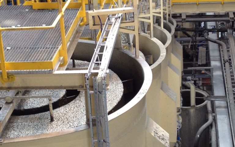
As design criteria go, removing the froth layer from froth flotation makes a bold statement. The fact that such a device not only exists, but has 50 operating installations, attests to the pressure on industry to find new solutions in the face of modern challenges. Low grades, complex ores and rising energy costs have prompted the development of entirely new flotation vessels, improvements to existing technology, and new thinking about flotation flowsheets.
The froth-free flotation vessel comes by way of Eriez Flotation Division, which patented it in 2002 and marketed it under the name HydroFloat. It is intended specifically for an innovative flowsheet that addresses one of the biggest problems mining operations face: With more tonnages to process, and more fine-grained ore, comminution is demanding ever more energy. If flotation circuits could handle coarser particles, then energy could be saved in the comminution circuit.
“Most mining companies are dealing with declining ore grades and complex mineralogy,” said Barun Gorain, director of Barrick Gold’s Strategic Technology Solutions Group. “The real problem is that more than 99 per cent of what we actually mine in the gold industry is considered waste.” He said that coarse particle flotation could allow mines to reject some waste earlier in the value chain, which will help reduce capital and operating costs.
WATCH: An introduction to the staged flotation reactor
Unfortunately, the conventional flotation cell achieves high recovery only in limited size ranges. For example, a sulfide ore might float very well at 90 to 120 microns, but not at 50 or 150 microns.
The research to date has identified two main reasons for the upper limit on floatable particle sizes. First, coarser particles tend not to have as much surface mineralization to attract bubbles.
Second, even if they are able to attach, they tend to detach again. In most conventional tank designs, an impeller at the bottom creates turbulence that helps bubbles and particles collide; the bubbles rise up through a quiescent zone and congregate in a froth layer at the top.
Graeme Jameson, laureate professor at the University of Newcastle in Australia, explained that if particles are hanging on to bubbles spinning around in liquid vortices at 100 revolutions a second, there is some critical size at which a particle will simply detach from the bubble.
High-energy turbulence is great for small-particle recovery, and by design the existence of turbulence is what keeps particles of all sizes in suspension. But that turbulence also discourages coarse particles from floating.
“The coarser the particles you’ve got, the faster you’ve got to stir the liquid to keep them off the bottom of the vessel,” he said. “So it’s a self-defeating piece of equipment from the point of view of trying to float coarse particles.”
Fluidized beds
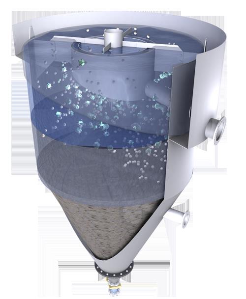 Eriez’s HydroFloat can float particles up to 2,000 microns. While the technology is familiar at potash operations, its installation at metal mines is a recent development. Courtesy of Eriez
Instead of an impeller, Eriez’s HydroFloat uses a fluidized bed to lift up coarse ore particles. Fed from the top, the vessel has a water inlet about two-thirds of the way down. As coarse particles sink to the bottom, the constant flow of water gently pushes them back up, continuously disrupting a region that is about 65 per cent solids. The water has been treated with compressed gas and a frothing additive to generate bubbles the coarse particles can attach to. While mineralized particles float into the overflow launder, coarse gangue settles to a dewatering zone in the bottom third of the vessel. When that zone reaches a certain density, its contents are released into the underflow outlet.
Ken Roberts, global sales director at Eriez, said that HydroFloat can extend flotation up to 400 or more microns. In some sulfide ores, it has recovered two-millimetre particles – translating to 2,000 microns. Moreover, he said, “We’ve proven with research with the University of Utah that we can float a particle with two per cent surface mineralization showing.”
HydroFloat is explicitly not intended to float fine particles. The idea is that it would be part of a split circuit, presorted into coarse and fine, with technologies tailored to each. The practice has been proven in non-metal ores like potash and diamonds; Eriez has just been broken into the metals market in the last couple of years.
Jameson has been doing lab work on his own fluidized-bed solution since 2006. His design adapts the eponymous Jameson Cell he patented in the late 1980s. In contrast to the HydroFloat, his cell treats fine and coarse together. The flotation feed cycles past an airjet first, where it encounters the high energy useful for attaching fine particles to bubbles. “That’s like the Jameson Cell, actually,” he said.
Then it flows into a fluidized bed, where the lower-energy environment allows coarse particles to attach. The ore-laden bubbles float up to a froth layer and overflow into a launder. A recycle line takes liquid off the top and recycles it into the base to be used for fluidization. Any fine particles washed out in the recycle line get another go at attaching to a bubble near the base. Fine gangue tends toward an overflow outlet.
A year ago, Jameson got his hands on a porphyry copper ore from South America, and his recently completed test work shows encouraging results. “We can get 100 per cent recovery up to about 300 microns,” he said.
Now Jameson is looking for a mine site willing to trial a full-scale installation of about 50 to 100 tonnes per hour. “The point of that size is that the single unit is reasonably easy to handle and to build,” he said. “You can take it to a site on a truck and install it there and do your testwork, and then you’ve got something you can reliably scale up from.”
Build it bigger – but smarter
Although proven technology supports floating coarse ore, that is nowhere near the norm. “The mining industry has a history of addressing dropping feed grades and higher costs by leveraging economies of scale,” said Walter Valery, global director of consulting and technology for mining and mineral processing at Hatch. The tendency is to “treat large tonnages, grind all the material finely and let the downstream separation processes sort it all out. However, this is generally very inefficient and is neither responsible nor viable during downtimes.”
Major equipment suppliers meet that demand by designing ever-bigger flotation cells. Thirty years ago, a cell 30 cubic metres in volume would have been unusually large. Now, 300-cubic-metre cells are commonplace. Outotec has a 500-cubic-metre cell in operation and several 630-cubic-metre cells in delivery, while FLSmidth has one 660-cubic-metre cell in operation.
Building one big tank does provide energy economies of scale. That shines especially bright for mining companies newly interested in the energy cost of flotation – previously a major theme only in comminution, but now entering focus as cost pressures generally intensify and flotation tonnages rise.
“When we double the size [of a tank], we get down by at least 10 to 20 per cent energy in practice,” said Antti Rinne, vice-president of beneficiation sales at Outotec. “That’s a huge amount of money in most countries in the world at the moment.”
That gradual scale-up comes with downsides. If the volume of the tank increases, the turbulence will not necessarily reach a commensurate height, which makes at least some of the extra tank volume a waste of space, steel and money.
“The proportion of the cell that is highly turbulent has decreased significantly as the size of flotation cells has dramatically increased over the last 20 years,” said Erico Tabosa, minerals processing engineer at Hatch.
FLSmidth has addressed this problem through its new nextSTEP impeller design, which was developed to eliminate “dead” spaces without turbulence. As a result, the new design also makes the machine more energy efficient. “We found that we are consistently lower in power when compared to other forced-air flotation machines,” said Asa Weber, flotation technology director at FLSmidth.
FLSmidth’s other major innovation is its Hybrid Energy circuit configuration, which addresses a problem of inconsistency in float cells. Because some ore is being recovered in each cell of a circuit, the mineralogical characteristics are changing from cell to cell but the cell design itself is not.
Outotec also developed ways to scale up while maintaining energy efficiency. Its own novel impeller designs, introduced in 2007, include a rotor/stator with similar turbulence-distributing benefits, called FloatForce. Outotec also invented an auxiliary impeller, called FlowBooster, that further improves mixing in the tank with very low additional energy.
Significant effort has gone into finding the best impeller speed for the specific ore and application. “We’ve been doing a lot of work in recent years looking at variable speed drives on flotation cells,” said Ben Murphy, technology director of flotation at Outotec. The first large cells running operations with a variable speed drive were installed about five years ago. Since then such installations have shown they can maximize energy use, recovery or sometimes even both.
“The interesting thing is we’ve actually been able to drill down a lot of the speed optimization and the energy reduction work to small cells,” added Murphy. “Which is kind of neat; it doesn’t always work that way.” For a small operation relying on diesel generators in a remote location, that could save real money.
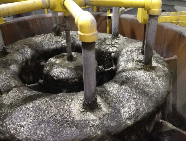 To float the same amount of material, the SFR requires less power and a smaller plant footprint than a conventional flotation cell. Courtesy of Woodgrove Technologies
Separate chambers
Barrick uses large conventional cells at its operations. But it is also working with different consortiums to develop “the next generation” of more efficient flotation machines, according to Gorain. “Economies of scale still works for some ores, but for low grade complex ore bodies, these conventional cells are approaching their technical limits or their benefits are only marginal at best,” he said.
The consortium sponsored work on a new design by Woodgrove Technologies. Instead of separate zones in one vessel, the staged flotation reactor (SFR) divides the flotation process into three chambers: a turbulent particle collection unit, a quiescent bubble disengagement unit, and a similarly quiescent froth recovery unit. Every SFR is custom-built for each mine’s projected ore characteristics.
“We look at the grade and tonnage over the life of the mine, and then we design the froth recovery unit to manage the weighted distribution of metal units over this time,” said Glenn Kosick, president of Woodgrove Technologies. “For instance, if you’re on the back end of a bank of standard flotation machines, you might be removing 0.3 to 0.5 tonnes per hour per square metre. Whereas with this machine, you might be running at 2.5 to three tonnes per hour per square metre.”
Kosick said the SFR’s efficient design cuts its energy use almost in half compared to a conventional flotation cell, and its limited use of floorspace makes it cheaper to install. “We’ve been selling it on the reduction in capital and operating costs,” he said. But its design also promotes better selectivity due to the large reductions of air used in these machines when compared to tank cells.
“The data we’re getting back at full scale is showing us that we can float coarser material by constraining surface area, which results in very stable froths and short transport distances,” said Kosick. The coarsest cell operating now is running at a feed p80 of about 230 microns; the finest one is at 20 microns.
Twenty-two SFRs have entered operation since 2010; more than 130 are under design. After a few successful installations at small mines, the consortium funded a trial scale-up to 930 tonnes per hour at Vale’s Sossego copper mine in Brazil. One of the consortium companies recently awarded Woodgrove the detailed engineering for an installation at a 95,000 tonne-per-day copper project in Chile.
Combining solutions
These new solutions are often presented, and can be installed, as discrete projects. But they are most effective when seen holistically. For example, Woodgrove recently merged with the process control supplier Portage Technologies, allowing it to deliver equipment and process monitoring as one package. Woodgrove can now offer a froth characterization system to measure froth velocity, stability and colour; and bubble size, count and density, and it can provide timely suggestions for changes to equipment settings. Additionally, its upfront grinding and cyclone control can stabilize surges and prevent rocks from reaching the flotation circuit.
On a larger scale, innovative flowsheet designs and reagent schemes are equally as important as the need for efficient flotation equipment. For example, Barrick is using its own patented flowsheet for a very complex refractory gold ore body. The process (“Mill-Chemistry-Float-Mill-Chemistry-Float”) involves floating the coarser particles in the feed first, regrinding, and then floating the fines but enabled with appropriate chemistry to suit the coarse and fines separately.
The consultants at Hatch, like many working on research and innovation, suggest adopting a mine-to-mill flowsheet design tailored to a particular set of ore bodies.
A reinvented flowsheet might start with more targeted blasting; it might intersperse flotation with grinding. Kristy Duffy, a minerals processing engineer at Hatch, suggested that the new coarse flotation technologies might be useful in a pre-concentration stage to remove coarse gangue. The stages might run: coarse grind, pre-concentration flotation, grind, rougher flotation, regrind and cleaning flotation.
Gorain agrees that it could potentially be of use. “Non-flotation-based pre-concentration is actually much more attractive, because you’re trying to deal with the waste right in the mining before any major energy intensive comminution is pursued,” he said. Yet if the ore mineralogy is too widely and finely disseminated for other methods, then he thinks flotation could potentially be an effective first concentration step.
More widespread interest is directed toward ore sorting, which can help toss out gangue early on and features heavily in mine-to-mill discussions. Roberts of Eriez said that several majors were investigating it hand-in-hand with a potential HydroFloat installation.
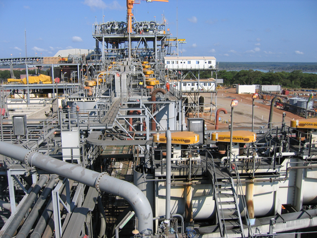 This Barrick operation uses large conventional cells along with a Jameson cell for recovering coarse liberated particles.Courtesy of Barrick Gold
The downturn’s effects
The last several years of prolonged financial difficulties for the industry have forced some forward movement on innovation, as many projects simply would not be viable without new approaches. “I met with two majors that are on a joint venture in South America probably about a month ago and showed them not only the HydroFloat, but some other technology we have,” said Roberts. “And that was the whole point of the meeting: ‘Tell us what you have that’s new.’ Five, ten years ago, nobody would ever say that.”
Woodgrove Technologies is also keeping busy during the downturn – without having to market itself, according to Kosick. “We’re hiring on almost a weekly basis here to try to keep up with the demand,” he said.
But the downturn has also stifled research that could produce new innovations. “Most R&D divisions of companies have been severely affected by the mining downturn,” said Sergio Vianna, a minerals processing engineer at Hatch. “Therefore, there are a scant number of new solutions developed in mineral processing in the last few years.”
To help size and select conventional cells, Hatch would like to have a detailed study on the rate at which froth can stably transport recovered minerals over the lip of the float cell. But Vianna has doubts that such a study can happen in the current research climate.
Kym Runge, principal research fellow at the Julius Kruttschnitt Mineral Research Centre (JKMRC) at the University of Queensland in Australia, is concerned that Australia’s formerly healthy ecosystem of research centres, mine sites and consultancies is in danger, if trends continue, of being cut too far to spring back. Many global leaders in mineral processing have passed through JKMRC or use tools developed there.
But research is continuing where it can. “We have a lot of other technologies which we’re working on,” said Barrick’s Gorain. “Obviously they are highly confidential, so we won’t be able to talk about it. But in general, the whole idea is to develop solutions for various complex ore bodies.”
Runge is working on a number of research projects. Progress made by equipment manufacturers notwithstanding, she thinks there is much more to understand about how turbulence affects flotation in the bigger cells. “A lot of people have just changed one variable and seen correlations and made conclusions from that,” she said.
She also sees a need to simulate the type of integrated, novel flowsheet envisioned at JKMRC. “Because they are low-risk beasts, the mining industry,” she said, “so being able to evaluate ‘What is going to be the economic benefit of putting a coarse particle flotation unit in the middle of my grind?’ will enable that to be adopted.”
Asked what flotation circuits would look like in ten years’ time, Runge was conservatively optimistic. “I’m hoping that we’ll start to see some of these new technologies start to be adopted,” she said. “I know we’ll be treating higher throughputs. And so they will need to get bigger, but hopefully we’ll also start to do things a little smarter.”
More Technology
The automation revolution
There is no doubt the future of mining is automation. But what does that look like, and how will we get there?
A short solution for the long haul
The sensors are in place and the data are pouring in. But what’s the most effective way to understand and act upon that information to optimize operations?

